Third-year electronics, electrical engineering and control student at Sorbonne University, with a mathematics minor. I design circuits and robotic prototypes, from sensors to embedded software. I also share my photography and 3D work.
Electronics, robotics and software: my projects, design choices and current progress.
Photography
3D modelling
About
I am Benjamin Piras, a third-year student at Sorbonne University, majoring in electronics, electrical engineering and control (EEA), with a mathematics minor. I am interested in the complete system: sensors, circuits, acquisition, programming and control.
StudiesThird-year EEA major, mathematics minor — Sorbonne University
During my internship at the Institute of Intelligent Systems and Robotics (ISIR), I worked on an instrumented robotic hand prototype. From component selection and PCB design to sensor processing, this experience brought electronics and robotics together in one project.
Wiring and programming of analogue inputs and visual feedback.
Technologies
Arduino · joystick · servo motor · LED
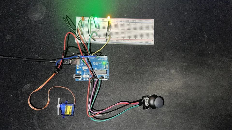
This Arduino joystick servo LED control demonstrates how to use analog inputs and LEDs for real-time feedback.
They haven’t joystick in Tinkercad, so I’ve added 2 potentiometers for illustrating the schema, but It’s the same, (VRx → A1, VRy → A2)
Objective:
This project aims to control various analog and digital inputs/outputs through an actuator (the joystick), with visual feedback provided by a set of LEDs. It demonstrates how to interpret analog signals to control a servo motor and reflect system states in real time.
The LED system complements this interaction:
🔴 Red: indicates that the servo is idle
🟢 Green: blinks when the servo is moving (X axis)
🟡 Yellow: blinks only when the joystick is moved along the Y axis
Components used:
1x Arduino UNO
3x Led (different colors)
1x Joystick (or 2x Potentiometers)
1x SG90 servo motor
3x 220Ω Resistors
Jumper wires, breadboard
1x Screwdriver for screw of the servomotor
How it works:
The X-axis potentiometer (simulating VRx) controls the servo position via analog input on A1.
When the position changes, the green LED blinks and the red LED turns off.
When there’s no movement, the red LED stays on, and the green LED stays off.
The Y-axis potentiometer (simulating VRy, connected to A2) is monitored separately. If movement is detected, the yellow LED blinks during activity.