
My project is to connect a LED strip to HomeKit using an ESP32, Apple’s smart home service that lets you control devices from your iPhone, wherever you are. I divided the project into three parts to gradually test and implement the system.
First, I’ll test the code and connections with a single LED (on/off control). Then, I’ll implement PWM (Pulse Width Modulation) to control the LED’s brightness (from 0 to 100%).
Second, I’ll use an RGB LED, which is more complex since it requires controlling each color channel with PWM through HomeKit.
Final (Later): I’ll wire up the actual LED strip. For that, I’ll need to precisely understand its voltage and power requirements.

I will include all documentation, schematics, and code I’ve used to complete the project.
Requirements:
- ESP32-D (for me but you can use a lot of another ESP32)
- Led (for myself blue)
- 220 Ω Resistor
- 2 Wires
1. Try with 1 led (On/Off + PWM)
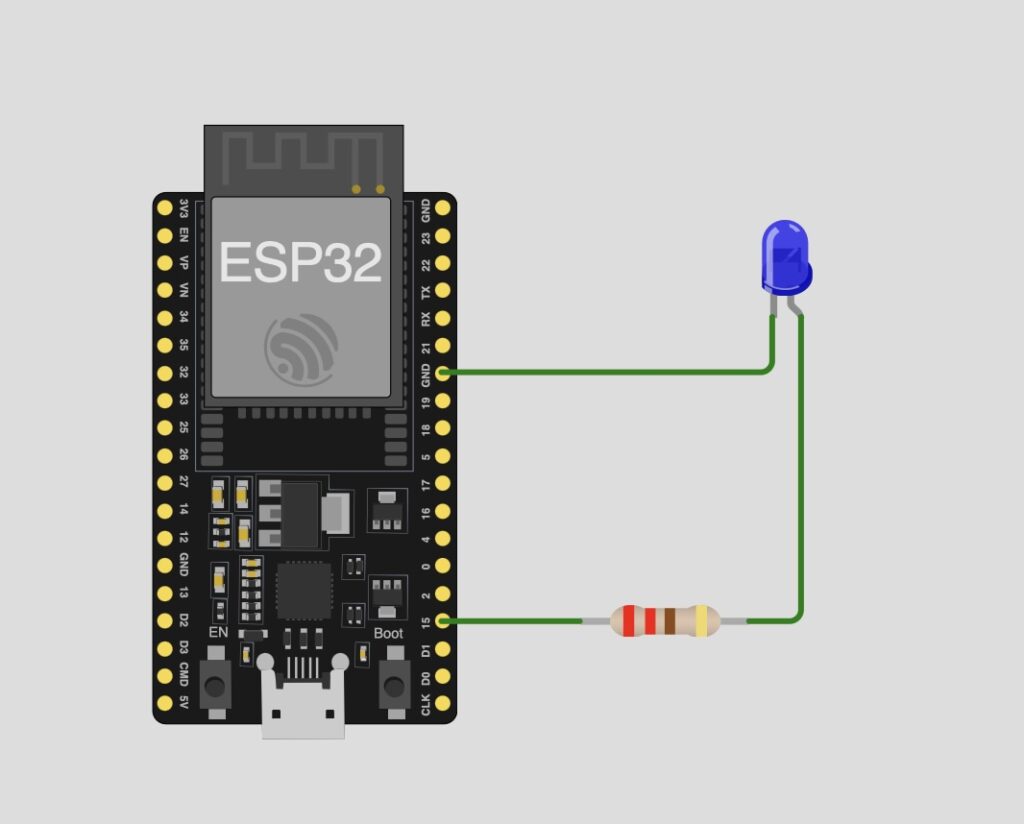
1. Connection
We connect the Led (The longest pin of the led is the Anode, the + you need to connect it to 220 Ω resistor because we want current, not voltage. and the other pin the Cathode (-) need to GND. I've plug the (+) on D15 because he has the PWM.
2. Code
To write the code, we use the HomeSpan library, which significantly simplifies development. When you upload the code to your ESP32, you’ll need to connect it to your Wi-Fi network. Open the Serial Monitor, type « W », then select your network by its number and enter your Wi-Fi password (SSID). This step is essential because the ESP32 will use your Wi-Fi to communicate with your iPhone through HomeKit, allowing you to control the LED (on/off, brightness, color, etc.).
#include <Arduino.h>

struct LED : Service::LightBulb {

  int ledPin;
  SpanCharacteristic *power;
  SpanCharacteristic *brightness;

  LED(int ledPin) : Service::LightBulb() {

    power = new Characteristic::On();
    brightness = new Characteristic::Brightness(100);

    this->ledPin = ledPin;

    pinMode(ledPin, OUTPUT);

    // PWM (We need to use ledcAttach it combine ledcAttachPin and ledcSetup with an update)
    ledcAttach(ledPin, 5000, 8);  // 5 kHz, 8 bits

    ledcWrite(ledPin, 255);       // Max power (LED ON)
  }

  boolean update() override {
    if (power->getNewVal()) {
      int level = brightness->getNewVal();  // 0 to 100
      int pwm = map(level, 0, 100, 0, 255); //  0–255
      ledcWrite(ledPin, pwm);
    } else {
      ledcWrite(ledPin, 0);  // LED OFF
    }

    return true;
  }
};
The main files which contain the Bridge (to allow the Led to connect to the Home app)
the code is very strict and follows HomeSpan rules and ledc
#include "HomeSpan.h"
#include "LED.h"

void setup() {
  // Setup code here, to run once:
  Serial.begin(115200);

  homeSpan.setPairingCode("11122333");
  homeSpan.setQRID("111-22-333");

  homeSpan.begin(Category::Bridges, "HomeSpan Bridge");


  new SpanAccessory();
    new Service::AccessoryInformation();
      new Characteristic::Identify();
    new LED(15);

}

void loop() {
  // Main code here, to run repeatedly:
  homeSpan.poll();
}
🗂️ Download
3. Result
2. Try with RGB Led (On/Off + PWM + Colors)
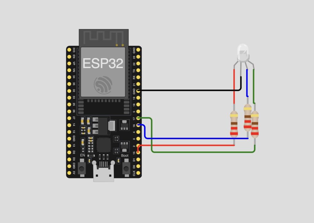
1. Connection
Each color of the RGB LED (red, green, and blue) needs its own resistor. Since this is a common cathode LED, the common pin should be connected to GND and I connect R -> D15, G -> D16, B ->D17 to make more fluid the code.

2. Code
It’s almost the same, but we need to include the two other colors (red and green), assign a PWM channel to each one, and let HomeKit know that this LED supports color control. I won’t show an extract of. I will just put the download link Here
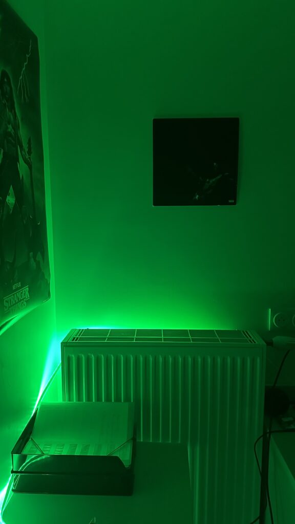
3. Result
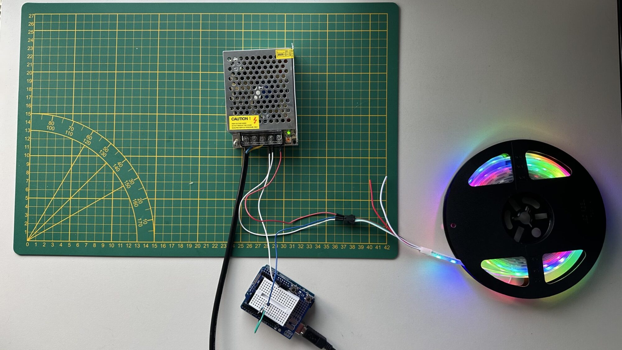
3. Test with the Led Strip
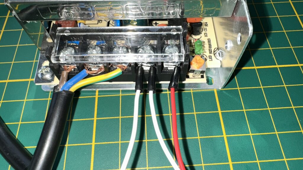
I received the LED strip, the power cable with 3 wires (blue, brown, yellow/green), and the 220V → 5V 8A power supply.
Since my LED strip has 120 LEDs, I calculated a maximum power consumption of about 33.5 W at 5V. An 8A supply is therefore more than enough, which is perfect.
1. Cable and check 5V
⚠️ Safety Warning:
- Do not connect 220V wires without proper connectors.
- Always use insulated terminals or screw connectors. Directly handling bare wires is extremely dangerous and can be fatal.
For the wiring:
Connect +V from the power supply to the +5V of the WS2812B LED strip.
Connect V- from the power supply to GND of the ESP32/Arduino and to the strip’s GND (usually the white wire).
💡 Tip: If you have a multimeter, you should measure the output voltage in DC mode: place the black probe on V- and the red probe on V+. You should read around 5V from the power supply.
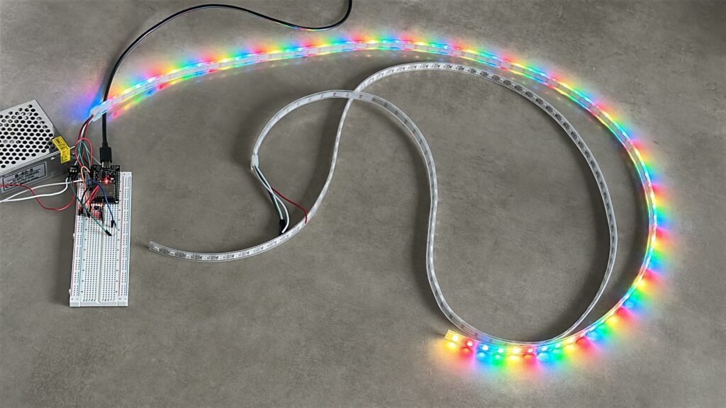
2. Code and Light !
You can use the library FastLED, because it’s easy to use !
#include <FastLED.h>

#define NUM_LEDS 60
#define DATA_PIN 9
#define BRIGHTNESS 170  // 50% brightness (0-255)

CRGB leds[NUM_LEDS];

void setup() {
  FastLED.addLeds<WS2812B, DATA_PIN, GRB>(leds, NUM_LEDS);
  FastLED.setBrightness(BRIGHTNESS);

  // Put on every led on the Colors
  for(int i = 0; i < NUM_LEDS; i++) {
    leds[i] = CRGB::Red;
  }

  FastLED.show(); // Put the color
}

void loop() {
  //Nothing here because the light stay on
}
3. Add Homespan library
Now we can see that the WS2812B works perfectly and the wiring is correct The next step is to upload the HomeSpan code to the LED strip, which I’ll do this weekend!
4. Use Wled-native
I’ve tried so many times to add the WS2812B on HomeKit and after a lot of try I’ve found Wled native, that a tool you can install into your ESP32 just go to this site and plug your ESP32 on your laptop and it’s done ! You just need to connect your esp to internet and install the app on your phone to control the led !
Install WLED (you need to use Chromium)
(That one of a lot of animation you can done with.. !)