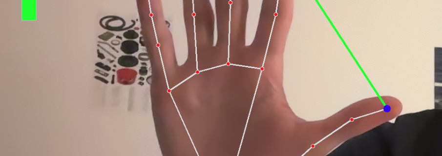
Catégorie : Arduino & Electronics Projects

A collection of hands-on Arduino and electronics projects including sensors, displays, servos, and interactive systems. Ideal for learning and prototyping

  • 3. Servo motor control with joystick and LED system

    This Arduino joystick servo LED control demonstrates how to use analog inputs and LEDs for real-time feedback.

    Breadboard wiring for Arduino servomotor control circuit

    They haven’t joystick in Tinkercad, so I’ve added 2 potentiometers for illustrating the schema, but It’s the same, (VRx → A1, VRy → A2)

    Objective:

    This project aims to control various analog and digital inputs/outputs through an actuator (the joystick), with visual feedback provided by a set of LEDs.
    It demonstrates how to interpret analog signals to control a servo motor and reflect system states in real time.

    The LED system complements this interaction:

    🔴 Red: indicates that the servo is idle

    🟢 Green: blinks when the servo is moving (X axis)

    🟡 Yellow: blinks only when the joystick is moved along the Y axis

    Components used:

    • 1x Arduino UNO
    • 3x Led (different colors)
    • 1x Joystick (or 2x Potentiometers)
    • 1x SG90 servo motor
    • 3x 220Ω Resistors
    • Jumper wires, breadboard
    • 1x Screwdriver for screw of the servomotor

    How it works:

    1. The X-axis potentiometer (simulating VRx) controls the servo position via analog input on A2.
    2. When the position changes, the green LED blinks and the red LED turns off.
    3. When there’s no movement, the red LED stays on, and the green LED stays off.
    4. The Y-axis potentiometer (simulating VRy, connected to A1) is monitored separately. If movement is detected, the yellow LED blinks during activity.

    Code and setup:

    • The servo_led_joysticks.ino file is fully commented and easy to follow.
    • Uses analog input from a joystick (VRx → A1, VRy → A2) to control logic and servo position.
    • A standard Servo library is used for smooth motor control.
    • Visual feedback is handled using 3 LEDs (idle, servo movement, and Y-axis activity).
    • Movement detection uses analog thresholds and angle comparison logic.
    • External power supply is recommended for the servo to avoid instability !!

    What I learned

    • How to use analog inputs to control both logic and actuators.
    • The importance of dead zones when working with joysticks.
    • How to implement real-time feedback through visual indicators.
    • How to simulate unavailable components (like a joystick) effectively.

    💾 Download the Arduino sketchservo_led_joystick.ino

    You can also check out my other Arduino project using a PIR sensor →Motion-Activated Stopwatch with HC-SR501 and 5641AS 4-Digit Display

  • 2. Arduino PIR Motion Sensor Stopwatch with 4-Digit Display

    Wiring of the Stopwatch with 4 Digit Display and Sensor

    Objective:

    Build a smart stopwatch displayed on a 4-digit 7-segment display (5641AS) and controlled by a motion sensor (HC-SR501).
    The timer starts on its own, pauses when motion is detected, and resumes only if a second motion is detected at least 20 seconds later.


    Components used:

    • 1x Arduino Uno
    • 1x 5641AS 4-digit display (common cathode)
    • 1x HC-SR501 PIR motion sensor
    • 4x 220Ω resistors (one per segment)
    • Jumper wires, breadboard
    • (Optional) Tweezer/screwdriver for adjusting the PIR

    How it works:

    1. The timer starts automatically at 0.
    2. When motion is detected, the timer pauses.
    3. A second motion, if detected after at least 20 seconds, will resume the timer.
    4. If the second motion is too soon, it will be ignored.

    The display shows minutes : seconds : tenths of seconds.
    For example, 1234 : 12 minutes and 34 seconds.


    Result:

    • A clean and readable live time display.
    • A motion-based pause/resume system.
    • A great hands-on practice with state logic and time-based decision-making on Arduino.

    Code and setup:

    • It uses the SevSeg library to easily control the display.
    • Code logic handles debouncing, timing, and PIR behavior cleanly.
    • Download project file (PIRMotionSensor.ino)

    To ensure fast and proper motion detection:

    • Turn the “Time Delay” right potentiometer fully counterclockwise on the PIR sensor.

    You can also check my LED control project with a joystick and servo for another use of sensors and feedback.

  • 1. Spotify Music on LCD1602 (Arduino UNO & Python 3.13)

    I built a small project to display the music currently playing on Spotify on a 1602 LCD screen using an Arduino UNO and a Python script.

    What it does

    • The first line of the LCD shows the song title and artist.
    • The second line shows the track duration.
    • If the title is too long, it scrolls smoothly across the display — like the animation on iPhones.

    What you need

    • 1x Arduino Uno
    • 1x LCD1602 (with or without I2C module)
    • 1x Potentiometer
    • 1x 220Ω Resistor for Anode
    • Jumper wires + Breadboard
    • Your PC with Python 3.13 installed

    Files

    • SpotifyLCD.py (Python script using the Spotify API and pyserial)
    • arduino_lcd_scroll.ino (Arduino code to scroll long titles and show duration)
    • Download project files

    How it works

    1. The Python script uses the Spotify Web API to get the currently playing track.
    2. It sends the track info via USB serial to the Arduino.
    3. The Arduino reads the data and updates the LCD accordingly.

    Extras

    • You can modify the Python code to also show the current time elapsed, album name, or even control playback.
    • The Arduino code supports basic horizontal scrolling and can be extended to add button control.

    Result

    Here’s a short video to show the LCD1602 in action, along with a screenshot of the Python script. The filming setup wasn’t perfect, but I hope you still enjoy it!